
Optimising selective soldering: speed, height and nozzle selection
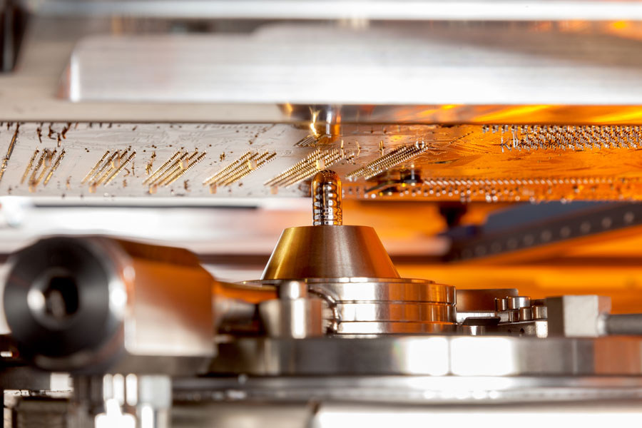
Selective soldering allows the soldering process to be configured very precisely. This is a major advantage: different components on the same PCB can each receive a treatment adapted to their specific requirements.
However, this flexibility does not mean that every parameter can be optimised independently. Soldering speed, soldering height, nozzle selection and heat transfer all influence each other. A change that improves cycle time, for example, may affect hole fill or increase the risk of bridging.
The right settings are therefore not found by maximising a single parameter, but by considering them as part of the same process.
Start with the right nozzle
Nozzle selection is often determined by the available space around the component to be soldered. But the nozzle also has an important thermal function.
A larger nozzle brings more molten solder into contact with the soldering area. This means more thermal energy is available to heat the component lead, the plated through-hole and the surrounding PCB.
A practical starting point is therefore:
Use the largest possible nozzle that the available space around the component allows.
This does not mean that the largest available nozzle is always the best choice.
When components are positioned close together, a smaller nozzle may be required to reach only the intended soldering area. The PCB layout therefore also determines how much room there is to optimise heat transfer through nozzle selection.
Take protruding lead length into account
The nozzle diameter is not the only important factor. The position of the PCB in relation to the molten solder also requires attention.
Through-hole components can have different protruding lead lengths. If a lead extends far below the PCB, sufficient clearance must remain between the lead and the nozzle.
If the lead touches the nozzle, it can interfere with the process.
At the same time, the molten solder needs to reach a sufficient height to make proper contact with the underside of the PCB and form the solder joint.
Soldering height and lead length therefore need to be considered together.
Stable mechanical positioning is essential. Small variations in the distance to the solder wave can affect the contact conditions and therefore the repeatability of the process.
How does soldering speed affect the process?
Soldering speed determines how long a particular area remains in contact with the molten solder.
A lower speed generally means a longer contact time. This allows more time for heat to be transferred to the joint.
This may be necessary for assemblies with a high thermal mass, such as a heavy connector or a PCB with a large amount of copper.
A higher speed reduces contact time and can shorten cycle time. However, sufficient thermal energy must still be available to form the joint correctly within that shorter period.
As a practical process range, speeds of approximately 3 to 7 mm/s are often considered. Higher speeds may be possible when the thermal conditions, flux and solder alloy allow it.
This should not be regarded as a universal setting.
The fastest setting does not necessarily result in the best process. The correct speed is the one that provides sufficient heat transfer and a reliable solder joint without unnecessarily extending the contact time.
More contact time is not always the best solution
When hole fill is insufficient, reducing the soldering speed may seem like a logical solution.
Moving more slowly does provide more time for heat transfer. But if the underlying problem is insufficient preheating, the nozzle is too small or there is insufficient flux, this approach mainly treats the symptom.
A longer contact time also means that the PCB and component are exposed to molten solder and high temperatures for longer.
When optimising the process, it is therefore better to first ask:
Why does this joint need more time?
It may be possible to solder the same joint faster and more reliably by improving heat transfer in another way.
Soldering height determines contact with the solder wave
The height of the solder wave relative to the PCB also affects the process.
The molten solder needs to make sufficient contact with the required area. If the soldering height is too low, contact may be insufficient. If it is too high, there is a greater risk of solder reaching areas that should remain untouched.
The geometry around the soldering point also needs to be considered, including protruding leads, neighbouring components and the available space around the nozzle.
There is therefore no single ideal soldering height. The objective is to achieve stable and repeatable contact between the solder and the PCB, without unnecessary interaction with surrounding areas.
The movement at the end of the soldering process also matters
What happens during contact with the solder wave is important, but so is the way the joint leaves the molten solder.
This is particularly relevant when drag soldering connectors with multiple leads.
As the joint leaves the solder wave, the molten solder forms a meniscus. The way this meniscus is broken can influence the amount of solder left behind and the formation of solder bridges between adjacent leads.
A controlled end to the soldering movement is therefore important.
One possible method is to lower the solder wave in a controlled manner at the end of the soldering path. This allows the meniscus to break gradually while the PCB remains in position.
This can help reduce bridging between adjacent solder joints.
Bridging is not always solved by changing one setting
When two adjacent solder joints are connected by excess solder, it can be tempting to identify a single machine parameter as the cause.
In practice, bridging can have several causes.
These include the movement as the PCB leaves the solder wave, soldering height, component geometry, nozzle selection and the properties of the flux and solder alloy.
It is therefore important not to change settings at random.
First determine at which point in the process the bridge is formed. Only then can you identify which parameter needs to be adjusted.
Optimisation means looking at parameters together
Suppose you want to shorten cycle time by increasing the soldering speed.
This is only possible if the joint still receives sufficient thermal energy during the shorter contact time.
You can therefore investigate whether:
- a larger nozzle can be used;
- preheating can be optimised;
- the soldering height is set correctly;
- sufficient flux is applied in the right location;
- the solder alloy is suitable for the required process conditions.
This is precisely why selective soldering cannot be reduced to a table of standard settings.
Changing one parameter can have consequences for several other parts of the process.
From machine settings to a stable process
The strength of selective soldering lies in the ability to precisely adapt the process to the PCB and component.
But having more adjustment options does not mean that more individual settings automatically result in a better process.
A robust process starts with understanding the function of each parameter:
nozzle selection influences heat transfer → soldering height determines contact → soldering speed determines contact time → movement out of the solder wave influences the final joint.
Only by considering these factors as a whole can you optimise both solder quality and cycle time.
One important part of the process still remains: the chemistry. The flux and solder alloy also influence the size of the process window and which settings are achievable.
Related trainings