
How do you create a good solder joint in selective soldering?
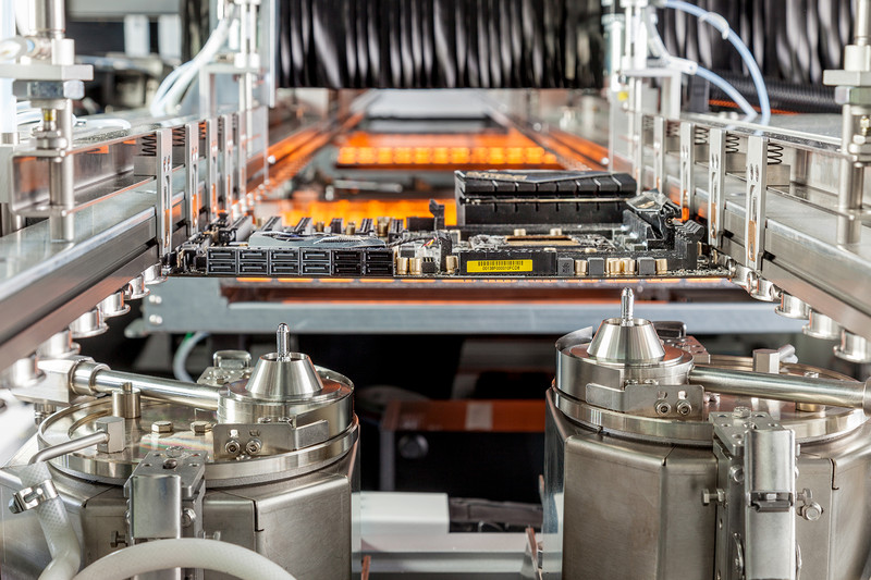
In selective soldering, only a specific area of the PCB comes into contact with molten solder. This allows through-hole components to be soldered locally without passing the entire PCB over a solder wave.
However, local soldering also means that sufficient flux and heat need to be delivered locally. The molten solder must be able to flow from the bottom of the PCB through the plated through-hole and properly wet both the component lead and the barrel of the hole.
Whether this happens successfully is not determined by a single setting. Flux, heat transfer, the relationship between lead and hole, and the thermal mass of the assembly all need to work together.
What happens during soldering?
A good solder joint starts before the PCB comes into contact with the molten solder.
Oxides may be present on the solderable surfaces, making proper wetting more difficult. Flux helps remove these oxides and supports contact between the molten solder and the base metal.
Sufficient heat must then be transferred to keep the solder molten as it moves up through the plated through-hole.
The process can broadly be described as follows:
flux application → preheating → contact with molten solder → wetting and hole fill → solidification of the joint
A problem at any of these stages can affect the final solder joint.
Flux needs to reach the right area
In selective soldering, flux is applied locally, for example with a microjet fluxer. This makes it possible to apply a small amount of liquid flux precisely to the required area.
The aim is not simply to get flux onto the bottom of the PCB. The flux needs to reach the solderable surfaces where it is required.
Component geometry plays an important role here. If a microjet is aimed directly at the centre of a relatively thick lead, for example, the flux may hit the lead and be deflected. As a result, insufficient flux may enter the gap between the lead and the hole.
The flux can therefore be applied alongside the lead. Depending on the geometry, this can be done on one or both sides. With a connector, for example, one or more lines can be programmed alongside a row of leads.
Using more flux is not automatically better. Flux that spreads beyond the effective soldering area can leave residues in areas that are not reached by the soldering process.
The relationship between lead and hole plays an important role
The space between the component lead and the wall of the plated through-hole affects how flux and molten solder can move through the hole.
Capillary action helps this process.
As a practical guideline, the hole diameter can be approximately 0.5 mm larger than the diameter of the lead. This provides around 0.25 mm of space on each side of the lead.
If this space is too small, it can become more difficult for the flux to spread effectively through the opening and to achieve a robust soldering process.
A good selective soldering joint therefore does not depend solely on the machine. PCB and component design also influence the process window.
Why is sufficient heat so important?
Flux alone does not create a good solder joint. Sufficient thermal energy must also be available.
This becomes particularly important for assemblies with a high thermal mass, such as:
- thick multilayer PCBs;
- PCBs with large amounts of copper;
- large connectors;
- components with heavy or thick leads.
The PCB and component absorb heat from the molten solder. If too much heat is dissipated, the local temperature can drop too far. The solder may then fail to flow sufficiently through the plated through-hole.
The result can be insufficient hole fill.
The solution is not necessarily to simply increase the solder temperature. First, you need to understand where the heat loss occurs and which process parameter is best suited to compensate for it.
Preheating helps control the thermal load
Preheating raises the temperature of the PCB before the actual soldering process begins.
This reduces the temperature difference between the assembly and the molten solder. The local solder wave therefore needs to transfer less energy to bring the PCB, component lead and plated through-hole up to temperature.
This can be particularly important for assemblies with a high thermal mass and can help achieve sufficient hole fill.
As a practical guideline, the top side of the PCB can be preheated to approximately 100 to 120°C, provided that the components and materials present can tolerate these temperatures.
This is not a universal setting. The appropriate preheat temperature should always be adapted to the specific assembly.
The nozzle also determines how much heat can be transferred
A nozzle does not only determine where you solder. Its selection also affects heat transfer.
A larger nozzle brings a greater volume of molten solder into contact with the soldering area. As a result, more thermal energy can be transferred.
A useful starting point is therefore:
choose the largest possible nozzle that the available space around the component allows.
When components are positioned close together, a smaller nozzle may be necessary to avoid contact with surrounding areas of the PCB.
The largest nozzle is therefore not automatically the right nozzle. The objective is to use the largest size that allows a stable and controlled process within the available space.
What should you do if hole fill is insufficient?
When the solder does not flow sufficiently through the plated through-hole, it can be tempting to immediately increase the temperature or extend the soldering time.
That may sometimes help, but it does not necessarily address the actual cause.
Instead, systematically check:
- Is sufficient flux actually reaching the through-hole?
- Is the lead-to-hole relationship suitable?
- Is the PCB sufficiently preheated?
- Is there a high thermal mass around the solder joint?
- Can the selected nozzle transfer enough heat?
- Are the flux and solder alloy suitable for the application?
Only once you understand where the limitation lies can you adjust the appropriate parameter in a targeted way.
A good solder joint is the result of the complete process
Selective soldering allows each solder joint to be approached very precisely. This provides considerable flexibility when adapting the process to different components and PCB layouts.
However, a reliable solder joint is not achieved by optimising a single parameter.
The flux needs to reach the correct surfaces, the geometry must allow capillary action, and sufficient heat must be available for the solder to form the joint correctly.
From this foundation, the machine parameters can be optimised further.
Factors such as soldering speed, soldering height and nozzle selection play an important role. These parameters affect not only cycle time, but also heat transfer and ultimately the quality of the solder joint.
Related trainings