How to prevent errors in the stencil printing process for SMD assembly
A component that is misaligned after reflow, a solder bridge or insufficient solder on a joint: when a defect becomes visible, its root cause is not necessarily found where the defect is detected.
In SMD assembly, an important part of the foundation is already laid during stencil printing. At this stage, the correct amount of solder paste must be deposited in the right position on each pad. Any deviations introduced here are carried into the subsequent stages of the assembly process.
However, a good print result does not depend on a single correct setting. Alignment, PCB support, squeegee pressure, print speed, contact between the PCB and stencil, and separation after printing all work together.
Preventing defects therefore requires looking at the entire printing process.
Why is stencil printing so important?
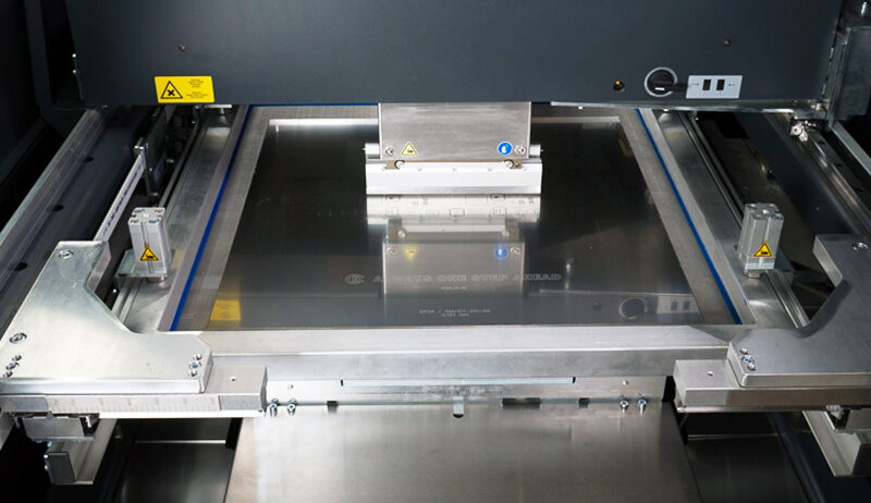
During stencil printing, the PCB is positioned against the stencil. A squeegee moves the solder paste across the stencil and fills the openings, or apertures. When the PCB and stencil are subsequently separated, the paste must release from these apertures in a controlled manner and remain on the pads.
The desired result sounds simple: well-defined deposits with a controlled amount of solder paste.
But several process parameters can affect that result. Insufficient contact between the PCB and stencil can allow paste to move between them. Incorrect squeegee pressure can result in insufficient aperture filling or other unwanted effects. Poor release can cause part of the solder paste to remain inside the stencil aperture.
The printing process therefore needs to be set up as a complete system.
Start with correct alignment
The stencil apertures need to be positioned correctly in relation to the pads on the PCB.
In modern inline stencil printers, horizontal alignment is typically performed automatically using camera systems and reference points. The machine uses these to determine the position of the PCB and stencil relative to each other.
However, horizontal alignment is only part of the equation.
The PCB and stencil must also fit together correctly in the vertical direction. If an unintended gap occurs on one side, this can affect the print result.
Correct positioning therefore means:
the stencil apertures are in the right position and the stencil and PCB make proper contact.
PCB support is a basic requirement
One factor that can easily be underestimated is PCB support.
During printing, the PCB is brought against the stencil while the squeegee applies force. If the PCB is not sufficiently supported, it can flex locally.
As a result, the distance between the PCB and stencil may no longer remain consistent across the board. Even when all other settings are correct, this can lead to an unstable printing result.
The source material therefore explicitly identifies PCB support as one of the key parameters in the printing process. The basic principle is simple: the better the support, the more stable the foundation for the printing process.
Supporting a single-sided PCB is relatively straightforward. With double-sided assemblies, it becomes more complex because components may already be present on the underside.
Fixed support pins must then not be positioned directly underneath a component. Depending on the product mix and production volumes, adjustable supports, spring-loaded systems or product-specific tooling can be used.
Ensure sufficient contact between stencil and PCB
In most applications, printing takes place without an intentional gap between the PCB and stencil: the PCB is brought into contact with the stencil.
Insufficient contact can allow solder paste to move between the PCB and stencil. This can result in paste being deposited outside the intended pads, potentially contributing to smearing, solder balls or bridging.
However, more pressure is not automatically better.
Excessive pressure between the PCB and stencil can increase mechanical stress and wear. The objective is therefore not maximum force, but stable and repeatable contact.
Squeegee pressure: enough, but no more than necessary
The squeegee needs to move the solder paste across the stencil and fill the apertures correctly.
This requires sufficient pressure.
If the squeegee pressure is too low, solder paste can remain on the stencil surface and the apertures may not be filled properly.
But again, more is not necessarily better.
Excessive squeegee pressure increases wear on the squeegee and stencil and may force solder paste between the stencil and PCB. According to the source material, scooping – where paste is partially removed from an aperture – can also be associated with excessive squeegee pressure.
A useful starting principle is therefore:
Set the squeegee pressure so that the stencil is clean after the print stroke, without applying unnecessary additional pressure.
This turns squeegee pressure from an isolated machine value into a setting that is evaluated based on the actual print result.
Print speed and squeegee pressure are related
The speed at which the squeegee moves across the stencil also affects the process.
Not every solder paste behaves in the same way at every print speed. Solder pastes can therefore be tested across different print speeds to determine a recommended process window.
Importantly, print speed cannot be considered entirely separately from squeegee pressure.
When print speed is increased significantly, the required squeegee pressure may also change. These parameters should therefore be evaluated together.
There is also a practical consideration for the production line: the stencil printer should not become an unnecessary bottleneck. However, printing as fast as possible is not the objective either. The required speed needs to remain within the stable process window of the solder paste and application.
After printing comes a critical step: release
Once the apertures have been filled, the PCB and stencil need to be separated again.
This movement may appear straightforward, but it directly affects how much paste actually remains on the PCB.
If the paste does not release properly from the stencil aperture, some of it may remain on the aperture walls. This becomes increasingly critical with small apertures and fine-pitch applications.
The separation speed – the speed at which the PCB and stencil move apart – is therefore an adjustable process parameter. The optimum value depends, among other things, on the solder paste and stencil geometry. In the paste tests discussed in the source material, separation speed is explicitly evaluated to determine where the best paste transfer is achieved.
A higher separation speed is therefore not automatically better. The goal is controlled release, with as much of the intended paste volume as possible remaining correctly on the pad.
Stencil cleaning is also part of process control
Even a well-configured process does not remain stable automatically.
Solder paste can accumulate on the underside of the stencil or remain inside the apertures. Many printers therefore use automatic understencil cleaning.
There is no universal cleaning interval. The source material emphasises that the required frequency depends on factors such as the product and the presence of fine-pitch structures. Cleaning may be required frequently in one application, while another may run for dozens of prints before cleaning is necessary.
The cleaning agent also deserves attention. It must be suitable for removing the solder paste being used and should not leave unwanted residues on the stencil.
A stencil that remains wet after cleaning can, in turn, affect the behaviour of the solder paste.
Check the result, not just the settings
A process can have the correct parameters on paper and still produce deviations.
Ultimately, the print result is what matters.
Ideally, the solder paste deposit should have:
- the correct position;
- sufficient and repeatable paste volume;
- clearly defined edges;
- a consistent surface;
- as little unwanted paste outside the intended area as possible.
Camera systems inside the printer can be used for inspection, but more extensive process control can be achieved with an SPI system (Solder Paste Inspection). This makes it possible to inspect the printed solder paste and detect deviations early in the process.
This matters because the earlier a deviation is detected, the fewer process steps a defective PCB will already have passed through.
A good print is the result of interaction between parameters
When stencil printing problems occur, it can be tempting to immediately adjust a single parameter.
More squeegee pressure. Slower printing. More frequent cleaning.
But changing one setting without understanding the cause can create another problem.
A stable stencil printing process therefore requires several conditions to work together:
- PCB and stencil are correctly aligned;
- the PCB is sufficiently supported in the right locations;
- PCB and stencil make repeatable contact;
- squeegee pressure and print speed are matched to each other and to the solder paste;
- the paste releases from the stencil apertures in a controlled manner;
- the stencil and apertures remain sufficiently clean;
- the final print result is monitored.
The goal is not to optimise every parameter individually, but to create a process window in which they work together to produce a repeatable solder paste print.
Preventing defects starts before pick-and-place
When a defect only becomes visible after reflow, it is important not to focus exclusively on the reflow oven or component placement.
The root cause may have occurred earlier in the process.
Stencil printing determines how much solder paste is deposited on the PCB, where that paste is placed and how repeatable the result is from one print to the next. This process step therefore deserves the same level of attention as the rest of the SMD line.
Stable SMD assembly starts with a stable solder paste print.
Related trainings