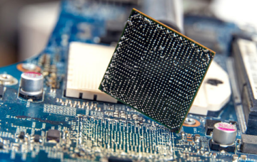
BGA rework: removing and replacing a defective BGA
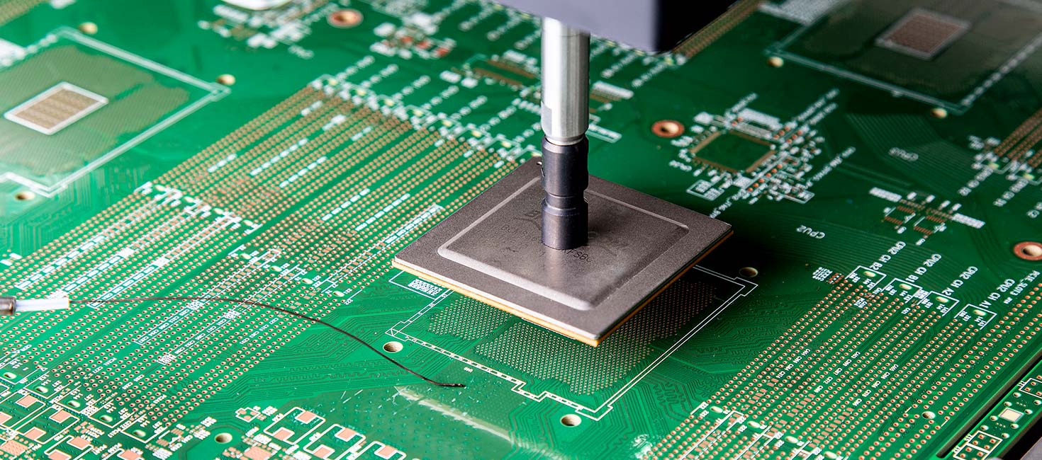
Replacing a defective BGA requires more control than desoldering a component with visible connections. The solder joints are located underneath the component, and during rework an already assembled PCB is exposed to another thermal cycle.
You need to apply enough heat to melt all the solder joints underneath the BGA without unnecessarily stressing the PCB, pads or surrounding components. Once the defective component has been removed, the footprint also needs to be properly prepared before a new BGA can be installed.
BGA rework therefore consists of several closely connected steps.
1. Assess the PCB before you start
There is no standard setting that works for every BGA and every PCB. Start by assessing the assembly you are working on.
A thick multilayer PCB with a large amount of copper, for example, absorbs and dissipates heat differently from a thin PCB. The size of the BGA and temperature-sensitive components nearby also influence the process.
Before starting, check factors such as:
- the thermal mass of the PCB and BGA;
- the solder alloy used;
- temperature-sensitive components around the BGA;
- the available space around the component;
- possible moisture absorption by the PCB or components.
Based on this information, you can determine how the PCB should be heated during rework and whether local protection is required.
2. Desolder the defective BGA in a controlled way
During desoldering, all solder joints underneath the BGA must be liquid before the component is lifted.
This is important. If some of the solder has not fully melted and force is applied to the component, pads can be pulled away from the PCB.
A BGA rework station therefore uses top and bottom heating. Particularly with PCBs that have a higher thermal mass, bottom heating helps bring the assembly to temperature in a controlled way. Top heating can then apply heat more specifically to the BGA area.
A thermocouple positioned as close as possible to the BGA measures what is actually happening on the PCB. This means you are not relying solely on the set temperature of the heating element.
Only when the solder joints have sufficiently reflowed should the BGA be carefully lifted.
The temperature profile plays an important role here. We cover this separately in How do you create a temperature profile for BGA rework?
3. Clean and prepare the footprint
After removing the BGA, solder will usually remain on the pads. The footprint is therefore not yet ready for a new component.
Flux is applied first. The remaining solder can then be removed, for example using a soldering iron and desoldering braid or a suitable desoldering system.
Thermal exposure should also be limited during this step. Excessive heat or prolonged contact increases the risk of damaging the pads. According to Interflux, prolonged exposure to molten solder can also affect the copper of pads and PCB tracks.
Therefore, work with the lowest effective temperature and keep thermal exposure as short as possible.
After removing the excess solder, clean the footprint. The aim is to obtain a clean and sufficiently flat surface with intact pads.
4. Apply the appropriate flux or solder paste
Before placing the new BGA, the appropriate soldering chemistry needs to be applied.
Depending on the application, this may include liquid flux, tacky flux, solder paste or dip paste. These products have different properties and are not simply interchangeable.
Tacky flux, for example, has a higher viscosity and can help keep the BGA in position before reflow. Solder paste contains both flux and metal, meaning it adds additional solder to the joint. With dip paste, the BGA balls are dipped into a controlled layer of paste.
Residue also requires attention. Once the BGA has been placed, thoroughly cleaning underneath the component becomes difficult. The choice of chemistry should therefore take the required cleanliness after soldering into account before the rework process begins.
This subject deserves more detail, which is why we cover it separately in Which flux or solder paste should you use for BGA rework?
5. Position the new BGA
Once the footprint has been prepared and the selected flux or paste applied, the new BGA can be placed.
Because the connections are located underneath the component, accurate alignment is important. A BGA rework station can use an optical positioning system to align the BGA balls with the pads on the PCB.
The component is then carefully placed onto the footprint.
A correct temperature profile cannot compensate for incorrect positioning. Alignment and reflow are two separate requirements for a reliable connection.
6. Solder using a controlled temperature profile
The new BGA is then soldered according to a predefined temperature profile.
The aim is not to bring the component above the solder melting point as quickly as possible. The PCB and BGA need to be heated in a controlled manner, taking into account factors such as thermal mass, solder alloy and the maximum permitted component temperature.
Important parameters in BGA rework include the heating rate, time above liquidus and peak temperature.
The profile used to solder the new BGA does not necessarily have to be identical to the profile used to remove the defective component.
A profile should therefore preferably be measured and optimised on the actual assembly rather than applying a standard profile without verification.
7. Inspect the result
After reflow, the BGA may look correctly positioned from above, but the solder joints are underneath the component.
Depending on the application, the connections can therefore be further checked using methods such as endoscopic inspection, X-ray inspection and functional testing of the PCB.
Only after this inspection is the rework process complete.
BGA rework requires control over the complete process
Reliable BGA rework is not determined by a single temperature setting or one type of flux. Each process step affects the next:
- assess
- desolder
- clean
- apply flux or paste
- position
- solder
- inspect
Smans supports companies in setting up and optimising this process, from rework equipment and positioning to measuring and evaluating temperature profiles. Together with Interflux, the appropriate flux, tacky flux, solder paste or dip paste can also be evaluated for the specific application.
Related trainings